Square Drive Tool
Hydraulic Torque Wrench
Informations produit
Informations générales
NE PAS JETER - REMETTRE À L'UTILISATEUR
Utilisation prévue
Pour utilisation professionnelle uniquement.
Ce produit et ses accessoires ne doivent être modifiés en aucune manière.
Ne pas utiliser ce produit s'il a subi des dégâts.
Si les vignettes apposées sur le produit pour indiquer les données du produit ou des mises en garde ne sont plus lisibles ou se décollent, les remplacer sans attendre.
The product must only be operated and serviced by trained and qualified personnel.
Signalétique de sécurité
Les mots Danger, Avertissement, Attention et Avis ont la signification suivante :
DANGER | DANGER indique une situation dangereuse qui, si elle n'est pas évitée, entraînera des accidents graves voire mortels. |
AVERTISSEMENT | AVERTISSEMENT indique une situation dangereuse qui, si elle n'est pas évitée, pourrait entraîner des accidents graves voire mortels. |
ATTENTION | Le mot ATTENTION accompagné du symbole d'alerte de sécurité indique une situation dangereuse qui, si elle n'est pas évitée, pourrait entraîner des accidents mineurs ou modérés. |
AVIS | AVIS sert à aborder des pratiques sans rapport avec un risque d'accident corporel. |
Garantie
La garantie du produit expirera 12 mois après la mise en service initiale du produit et dans tous les cas au plus tard 13 mois après la livraison.
L'usure normale des pièces n'est pas comprise dans la garantie.
L'usure normale est celle nécessitant un changement de pièces ou autres opérations de réglage et de révision pendant l'entretien courant de l'outil pendant la période donnée (exprimée en temps, heures de fonctionnement ou autres).
La garantie du produit repose sur une utilisation correcte, un entretien normal et des réparations appropriées de l'outil et de ses composants.
La détérioration des pièces consécutive à un entretien inadéquat ou réalisé par des parties autres que Atlas Copco ou ses partenaires d'entretien agréés pendant la période de garantie ne sera pas prise en charge.
Pour éviter la détérioration ou la destruction de certaines parties de l'outil, il convient de procéder à l'entretien de ce dernier conformément aux périodicités d'entretien recommandées et de suivre les bonnes consignes.
Les réparations dans le cadre de la garantie ne sont effectuées que dans les ateliers de Atlas Copco ou par des partenaires d'entretien agréés.
Atlas Copco propose une extension de garantie et un entretien préventif à la pointe de la technologie par le biais de ses contrats ToolCover. Pour en savoir plus, s'adresser au représentant SAV local.
Pour les moteurs électriques :
La garantie ne s'appliquera que si le moteur électrique n'a pas été ouvert.
ServAid
ServAid est un portail qui est constamment mis à jour et qui contient des Information techniques, comme :
Informations réglementaires et sur la sécurité
Caractéristiques techniques
Instructions d'installation, d'utilisation et d'entretien
Nomenclatures de pièces détachées
Accessoires
Plans cotés
Veuillez consulter : https://servaid.atlascopco.com.
Pour plus d'Informations techniques, veuillez contacter votre représentant local Atlas Copco.
Fiches de données de sécurité FDS
Les Fiches de données de sécurité décrivent les produits chimiques vendus par Atlas Copco.
Veuillez consulter le site Web Atlas Copco pour plus d'informations www.atlascopco.com/sds.
Pays d'origine
Pour le Pays d'origine, veuillez vous reporter aux informations figurant sur l'étiquette du produit.
Plans cotés
Les Plans cotés sont soit disponibles dans l’Archive des plans cotés, soit sur ServAid.
Veuillez consulter : http://webbox.atlascopco.com/webbox/dimdrw ou https://servaid.atlascopco.com.
Aperçu
Caractéristiques techniques produit
Les Caractéristiques techniques produit peuvent être consultées sur ServAid ou sur le site Web d’Atlas Copco.
Veuillez consulter : https://servaid.atlascopco.com ou www.atlascopco.com.
Présentation de l'entretien
Recommandations pour l'entretien
Il est recommandé de procéder à une maintenance préventive à intervalles réguliers. Voir les informations détaillées sur la maintenance préventive. Si le produit ne fonctionne pas correctement, le mettre hors service et le contrôler.
Si aucune information détaillée à propos de la maintenance préventive n'est incluse, suivre ces directives générales :
Nettoyer les pièces appropriées avec soin
Remplacer toute pièce défectueuse ou usée
Fonctionnement
Directives d'ergonomie
Étudiez votre poste de travail en lisant cette liste de directives générales d’ergonomie afin de détecter des possibilités d’amélioration quant à la posture, au placement des composants ou à l’environnement de travail.
Faites des pauses fréquentes et changez fréquemment de position de travail.
Adaptez le poste de travail à vos besoins et à la tâche à réaliser.
Organisez-vous de manière à avoir un rayon d’action adapté en déterminant l’endroit où les pièces et outils doivent être positionnés, afin d’éviter les charges statiques sur les muscles.
Utilisez des équipements de poste de travail tels que des tables et des chaises adaptées à la tâche à réaliser.
Évitez les positions de travail à une hauteur plus élevée que le niveau de l’épaule ou nécessitant un maintien statique pendant les opérations d’assemblage.
Pour travailler à une hauteur plus élevée que le niveau de l’épaule, réduisez la charge statique sur les muscles en réduisant le poids de l’outil, à l’aide par exemple de bras de serrage, d’enrouleurs de tuyau souple ou de répartiteurs de charge. Il est également possible de réduire la charge statique sur les muscles en tenant l’outil près du corps.
Faites des pauses fréquemment.
Évitez les postures extrêmes du bras ou du poignet, en particulier lors des opérations nécessitant un certain effort.
Arrangez-vous pour avoir un champ de vision approprié qui nécessite un minimum de mouvements des yeux et de la tête.
Utilisez un éclairage adapté à la tâche à réaliser.
Sélectionnez l’outil adapté à la tâche à réaliser.
Dans les environnements bruyants, utilisez un équipement de protection auditive.
Utilisez des outils insérés et des consommables de grande qualité, afin de limiter au maximum l’exposition à des niveaux excessifs de vibrations.
Mode d’emploi
Electric Connections
Ensure proper power availability to prevent motor failure or dangerous electrical overloading. Use the recommended amperage listed on the motor nameplate. Do not use electric pump if ground is not connected on plug.
Limiter la longueur de cordons prolongateurs et s’assurer qu’ils sont d’une taille de fils adéquate et possèdent une terre.
Extension cord should be #10 AWG gauge.
Configuration générale
All our hydraulic torque wrenches are supplied completely assembled, ready for use. An Atlas Copco hydraulic power pack, for use with your Atlas Copco hydraulic torque wrench, is recommended to provide the speed, pressure and portability that make your Atlas Copco System efficient and accurate.
The accuracy of your Atlas Copco hydraulic torque wrench is +/-3% based upon our manufacturer's specifications. This accuracy is certified through calibration tests conducted by Atlas Copco or any other qualified calibration facility whose program is traceable to the National Institute of Standards and Technology (N.I.S.T). We strongly suggest using Atlas Copco certified gauges (with a class 1 accuracy) to enhance the accuracy your torquing system.
Raccordements pneumatiques
Ensure that you have sufficient air flow (58 up to 100 PSI / 4 up to 7 bar) to operate you pneumatic pump. If in doubt, compare the pump manufacturer's recommended air flow rating prior to pressurizing pump. Improper air flow may damage the pump motor.
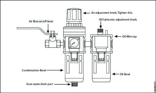
For best results use air hoses equal or larger than 3/4” internal diameter.
Use of a F.R.L. (Filter Regulator Lubricator) is highly recommended. Fill with oil and adjust the air admission with the adjustment knob.
Hydraulic Connections
Our hydraulic pumps are equipped with a zero-pressure relief valve. However, it could be possible that the retract side remain pressurized after the pump has been switched “off”. This trapped pressure prevents the user from loosening the retract-side fittings by hand. To release the pressure, simply push the black button on top of the solenoid. All fittings are free to be manually tightened.
Never disconnect or connect any hydraulic hoses or fittings without first unloading the wrench and the pump. If the system includes a gauge, double check the gauge to assure pressure has been released. When making connections with quick disconnect couplings, make sure the couplings are fully engaged. Les branchements filetés tels que les raccords, manomètres, etc. doivent être propres, solidement serrés et étanches.
Pression de service
The tool's maximum working pressure is 10,000 psi (700 bar). Make sure that all hydraulic equipment (pumps, hoses, couplers) used with this tool are rated for 10,000 psi (700 bar) working pressure. Review the documentation for the hydraulic pump in use to ensure pressure does not exceed 10,000 psi.
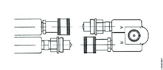
Connecting the System
The Atlas Copco hydraulic torque wrench and the power pack are connected by a 10,000 psi (700 bar) operating pressure twinline hose assembly. The safety ratio of the Atlas Copco hydraulic hose is 4/1. On each twin hydraulic hose, one line must be MALE-MALE and the other line must be FEMALE-FEMALE in order to assure a correct interaction between pump and machine. Connect the twinline hose to the swivel as shown:
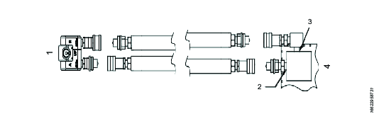
Référence | Description |
|---|---|
1 | Clé |
2 | Port A |
3 | Port 'R' |
4 | Pompe |
Check all coupler connections because, after the system has been pressurized, you will not be able to tighten the couplers by hand and using tools will damage the couplers.
Check all coupler connected properly with no gaps between collar and fittings. Never use spanners and other tools to tighten or loose couplers.
Ensure connectors are fully engaged and screwed snugly together.
Never use two twin hydraulic hoses between pump and machine. If so, you have the high pressure on the retract side and your machine will not work properly. To avoid tool malfunction, do not reverse connectors. Do not try to loosen the swivel assembly at any moment.
Operating Hydraulic Pump
Setting Working Pressure on the Pump
To set the pressure on the pump, follow this procedure:
Loosen the knurled locking ring below the "T" handle on the pump's external pressure regulator. Then turn the "T" handle counter clockwise (CCW) until it turns freely and easily.
Turn the pump "on". Using the pump's remote control pendant, push down the advance switch (or button on air pumps) and hold it.
While holding the pump in the advance mode, slowly turn the "T" handle clockwise and observe the pump pressure gauge rise.

Always adjust the regulator in order to increase the pressure up - Never down. Ne jamais agir sur le régulateur de pression hydraulique tandis que l’outil est appliqué.
When your gauge reaches 4,000 psi stop turning the "T" handle and let the gauge settle out.
If the pressure continues to rise (above 4,000 psi), release the advance button and back off your pressure slightly-by turning CCW on the "T" handle. Then re-depress the advance switch on you remote and slowly bring pressure up to 4,000 psi again.
When the pressure is correct, turn the pump "off" and tighten the knurled lock nut provided under the "T" handle. This sets pump pressure, which determines torque tool output.
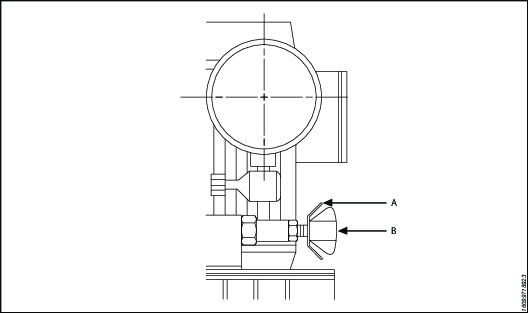
Référence
Description
A
Bague de blocage
B
T - Handle
Once your target pressure is set and locked, cycle the pump once more to ensure that your pressure setting did not change as you turned down the knurled knob.
Applying Torque to Wrench
Having set your target pressure, cycle the tool three or four times to full pressure. Cycling the tool ensures that the system is operating properly and removes trapped air, if any.
Verify that any impact sockets used are rated to accept the full torque output of the tool they are to be used with. Ensure the correct size impact socket for the nut A/F has been selected, placed on the square drive and secure with a locking pin and ring.
Place the tool and the socket on the nut, making sure that the socket has fully engaged the nut, check that the drive retainer is engaged.
Veiller à appuyer fermement le bras de réaction contre un objet fixe (c’est-à-dire un écrou voisin, une bride, un carter, etc.). When positioning the wrench, make sure that the hose connections are well clear of any obstructions and that all body parts are safely out of harm's way. Ensuite, et ensuite seulement, mettre momentanément le système en pression pour assurer le positionnement correct de l’outil. If it doesn't look or act right, stop and re-adjust the reaction arm.
Read Safety Instructions supplied with the torque wrench for further guidance on tool usage.
By pushing down on the remote control button in the advance position, the rear of the tool will be pushed back until its reaction arm will contact its reaction point.
Continue to hold down the button as the socket turns until you hear an audible "click" which will signify the hydraulic cylinder inside the tool is fully extended and will not turn the advance further.

Continuing to hold down the remote control button will result in a rapid build up of pressure to the point of where the gauge reads what was preset prior to applying the wrench.
The reading of full preset pressure after the cylinder is extended DOES NOT INDICATE that this pressure (torque) is applied to the bolt. It only indicates that the cylinder is fully extended and cannot turn the socket or the ratchet link further until the tool automatically resets itself.
Releasing the remote control button will retract the cylinder. The tool will automatically reset itself and the operator will hear an audible "click" indicating he can again push the remote control button and the socket will turn. Each time the cylinder is extended and retracted, it is called a cycle. Successive cycles are made until the tool "stalls" at the pre-set Torque/psi with an accuracy of +/-3%. Repeatability is +/- 1%.
Always attempt one final cycle to ensure the "stall" point has been reached.
Should the tool "lock-on" after the final cycle, push down on the remote control button once more (to build pressure) and, while maintaining this pressure, pull back on the external disengagement lever (RT) or reaction Pawl (RTX). Releasing the remote control while continuing to hold back on the pawl lever/reaction pawl will allow the tool to be removed easily.
Loosening Procedures
First, set the pump to 9,000 psi (Do not try directly at 10.000 psi). Change the drive and the reaction arm to the loosening mode (Left = Loose), assuring the reaction arm abuts squarely off a solid reaction point. Press and hold the remote control button down. Pressure will decrease as the socket begins to turn. As the cylinder extends fully, you will hear an audible "click". Release the remote control button, and the cylinder automatically retracts, at this time you will again hear the audible "click". Repeat this process until the fastener can be removed by hand.
If the bolt does not loosen with the above procedure, it is an indication that you need a larger tool to loosen the bolt.
Setting Torque
All Atlas Copco power packs operate at a pressure range from 500 to 10,000 psi and are fully adjustable. They have been engineered and designed for portability and high flow for increased speed. Before using your Atlas Copco power pack, check the following points.
Is the reservoir filled with oil?
Where is the closest electrical outlet at the job site?
Is there enough air pressure (60 to 100 psi) and Air flow at the job site? (Air units only)
Is the gauge mounted and rated for 10,000 psi / 700 bar?
Pression de service
The pump's maximum working pressure is 10,000 psi / 700 bar. Make sure all hydraulic equipment and accessories are rated for 10,000 psi / 700 bar operating pressure. Hydraulic pumps are available with higher pressure outputs, if not using an Atlas Copco power pack verify maximum operating pressure of the unit being used and ensure the system maximum operating pressure (10,000 psi / 700 bar) is not exceeded.
Hydraulic Connections
Never disconnect or connect hydraulic hoses or fittings without first unloading the wrench. Unplug the electrical cord of the pump, and open all hydraulic controls several times to assure that the system has been depressurized. If the system includes a gauge, double check the gauge to assure pressure has been released. When making a connection with quick disconnect couplings, make sure the couplings are fully engaged threaded connections such a fittings, gauges etc. must be clean and securely tightened and leak free.
Loose or improperly threaded couplers can be potentially dangerous if pressurized, however, severe over tightening can cause premature thread failure. Les raccords doivent être serrés de manière solide et étanche. Ne jamais prendre en main, toucher ou entrer en contact de quelque manière que ce soit avec une fuite hydraulique sous pression. L’huile qui s’échappe peut pénétrer la peau et provoquer des lésions. Do not subject the hose and potential hazard such as sharp surfaces, extreme heat or heavy impact. Do not allow the hose to kink and twist. Inspect the hose for wear before it is used.
Electrical Power
Check the proper electrical supply before connecting.
This motor may spark. Do not operate in an explosive atmosphere or in pressure of conductive liquids.
Do not use a power or extension cord that is damaged or has exposed wiring.
All single phase motors come equipped with a three prong grounding type plus to fit the proper grounded type electrical outlet. Do not use a two prong ungrounded extension cord as the pump's motor must be grounded.
Comparer la plaque signalétique du moteur à l'alimentation disponible pour éviter de griller le moteur ou de créer une surcharge électrique dangereuse.
Prior to Use
Check hydraulic oil (Use Atlas Copco maximiser range Grade 46) level to prevent possible pump burnout. Open the filler plug located on the reservoir plate. Look at oil fill level on the oil sight gauge. The oil level should be approximately 2" from the top of the reservoir plate- with motor off. Add oil as necessary. Do not mix different grades of oil. Make sure all desired gauge, valve, hose and quick coupler connections are tight and secure before operating. The use of a pressure gauge is required for normal pump operation. Mounted on the manifold, the gauge permits the operator to monitor the load on the wrench. Class1 certified calibrated gauges are available for most applications.
Operating Square Drive
Changing Drive Direction
To remove the square drive, push the round button on the drive retainer and gently pull on the square end of the square drive (for RT20, 25 & 50, push on the drive retainer while turning it counter-clockwise). To insert the drive in the tool, place the drive in the desired direction, engage drive and bushing splines, then twist drive and bushing until ratchet Spline can be engaged. Push drive through ratchet.
Push drive retainer button, engage retainer with drive and release button to lock the square drive in position.
Pas de bras de réaction.
All Atlas Copco hydraulic torque wrenches are equipped with a universal reaction arm. These reaction arms will absorb and counteract forces created as the unit operates. The reaction arm should extend in the same direction of the square drive; however, slight adjustments may be made to suit your particular application. The RT reaction arm is made of special aircraft alloy and is 360° adjustable.
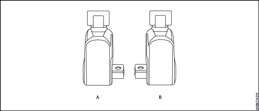
Référence | Description |
|---|---|
A | Right = Tight |
B | Left = Loose |
The standard RT reaction arm cannot be welded on and should not be modified.
The reaction arm for all RT Monobloc Housing is splined to slide over the rear (cylinder) portion of the tool. In operation, the reaction arm must be fully engaged and secured by inserting the spring loaded reaction arm lever at the base of the housing (end cap). S’assurer que le bras de réaction est entièrement engagé avant de lancer l’opération.
Setting Torque
Once the system is fully connected and proper power supply available, the operator may now adjust the pump pressure to the level needed for the application.
When tightening, use the manufacturer's specifications to determine the torque value which you will ultimately require.
Torque sequence may vary from plant to plant and even within individual plants, depending upon the gasket material, etc. Always follow local procedures.
Refer to the pressure-torque conversion table applicable to the tool which you intend to use, Torque chats are available on ServAId .
Square/Allen Drive Working Torque
Entraînement The square or hex drive of each drive is limited in its maximum output by its material and its engagement area. Since Atlas Copco uses a specially suited alloy-steel for its drive members, the following maximum torque output can be achieved without drive failure, provided the reaction member abuts close to the same plane as the nut to be turned.
If the reaction arm cannot abut on the same plane as the nut to be turned, less torque should be applied, as the additional side load has to be taken into consideration. When toque requirements are close in excess of the values listed above, use RT's/-9/ Sockets Hex-Drive with replaceable Hex Insert Bits.
RT series is available with square drive (standard) or option hexagonal/Allen drive. The table below reviews ideal working range for the respective drives.
Entraînement Inch or mm | Type d’entraînement | Pression de service maximum | Probable Failure | ||
ft lb | Nm | ft lb | Nm | ||
1/2" | hexagonale | 353 | 478 | 392 | 531 |
1/2" | Carré | 367 | 497 | 408 | 553 |
5/8" | hexagonale | 689 | 934 | 766 | 1038 |
3/4" | hexagonale | 1191 | 1614 | 1324 | 1794 |
3/4" | Carré | 1239 | 1679 | 1377 | 1865 |
7/8" | hexagonale | 1892 | 2565 | 2102 | 2848 |
1" | hexagonale | 2824 | 3827 | 3138 | 4252 |
1" | Carré | 2937 | 3980 | 3263 | 4422 |
1 - 1/8" | hexagonale | 4021 | 5448 | 4468 | 6054 |
1 - 1/4" | hexagonale | 5516 | 7474 | 6129 | 8304 |
1 - 3/8" | hexagonale | 7341 | 9948 | 8157 | 11053 |
1 - 1/2" | hexagonale | 9531 | 12915 | 10590 | 14350 |
1 - 1/2" | Carré | 9912 | 13432 | 11014 | 14924 |
1 - 5/8" | hexagonale | 12118 | 16420 | 13465 | 18245 |
1 - 3/4" | hexagonale | 15135 | 20508 | 16817 | 22787 |
1 - 7/8" | hexagonale | 18616 | 25224 | 20684 | 28027 |
2" | hexagonale | 22593 | 30613 | 25103 | 34015 |
2 - 1/4" | hexagonale | 32168 | 43588 | 35742 | 48431 |
2 - 1/2" | hexagonale | 44126 | 59791 | 49029 | 66435 |
2 - 1/2" | Carré | 45891 | 62183 | 50990 | 69092 |
12mm | hexagonale | 298 | 404 | 331 | 449 |
17mm | hexagonale | 847 | 1147 | 941 | 1275 |
19mm | hexagonale | 1182 | 1602 | 1313 | 1780 |
22mm | hexagonale | 1835 | 2486 | 2039 | 2763 |
24mm | hexagonale | 2382 | 3228 | 2647 | 3587 |
27mm | hexagonale | 3392 | 4596 | 3769 | 5107 |
32mm | hexagonale | 5647 | 7652 | 6275 | 8502 |
36mm | hexagonale | 8040 | 10895 | 8934 | 12105 |
41mm | hexagonale | 11878 | 16094 | 13197 | 17882 |
46mm | hexagonale | 16774 | 22730 | 18638 | 25255 |
50mm | hexagonale | 21542 | 29190 | 23935 | 32433 |
Maintenance
Instructions de maintenance
Recommandations d'entretien et de maintenance
Toujours porter une protection oculaire et du visage résistante aux chocs pour travailler avec l'outil ou à proximité, pour les réparations ou l'entretien de l'outil ou pour changer des accessoires.
Tous les travaux de vérification, d’entretien ou de réparation ne doivent être effectués que lorsque le système complet est à pression nulle.
Pour obtenir des performances optimales, contrôlez fréquemment l'état visuel de l'outil, du groupe d'alimentation, des flexibles, des raccords, des câbles électriques et des accessoires. Suivez toujours les instructions pour l’entretien de l'outil et de la pompe.
Conseils sur les intervalles d'entretien
Les clés hydrauliques peuvent être utilisées sans problème pendant de nombreuses années si le personnel est formé et respecte un programme d'entretien adéquat. Cependant, tous les outils s'usent avec le temps. Voici les facteurs qui influencent la durée de vie de l'outil :
Cadence de production élevée
Utilisation sous forte charge
Impacts
Fonctionnement dans des environnements sales, chauds ou humides
Différentes méthodes de réaction
Mauvais entretien
Il est recommandé de lubrifier et de réviser régulièrement la clé pour s'assurer qu'elle reste en bon état de marche. Des révisions plus fréquentes peuvent s'avérer nécessaires si l'outil est utilisé avec un couple élevé, des cadences élevées ou des durées de serrage importantes. Si la clé ne fonctionne pas correctement, elle doit être immédiatement retirée pour vérification.
Les intervalles d'entretien suivants ne sont donnés qu'à titre indicatif. Chaque cas d'utilisation et chaque application étant différents, il incombe à l'utilisateur final de mettre en œuvre une maintenance planifiée adaptée, spécifique à l'environnement de travail et à l'utilisation. Conservez un registre de l'utilisation des outils. Ce registre facilite la planification de l'entretien, de l'étalonnage et du remplacement des outils ou des composants.
Utilisation réduite
Exemple : Utilisation peu fréquente à basse pression, <40 % de capacité.
Lubrification : tous les 6 mois
Révision complète : tous les 12 mois
Utilisation normale
Exemple : Utilisation normale, <80 % de capacité.
Lubrification : tous les 3 mois
Révision complète : tous les 12 mois, y compris le remplacement de l'axe d'entraînement. Voir le paragraphe Lubrification.
Utilisation intensive
Exemple : Utilisation répétée à n'importe quelle pression ; utilisation >80 % de la capacité ; utilisation normale pour desserrer les boulons corrodés.
Lubrification : chaque mois
Révision : tous les 6 mois, y compris le remplacement de l'axe d'entraînement et du levier à cliquet. Voir le paragraphe Lubrification.
Remplacement des outils
Le propriétaire du produit doit mettre en œuvre un programme d'entretien pour la politique de remplacement des outils. Cette politique garantit que les outils en état sont remplacés avant qu'ils ne deviennent obsolètes. En raison des différents environnements opérationnels et des éventuelles incohérences dans l'entretien des outils, il est difficile de définir leur durée de vie.
Les signes visibles d'usure, tels que les rayures, les bosses ou les parties manquantes, indiquent que l'outil n'est plus utilisable. Outils d'entretien qui montrent des signes d'usure. Pour maintenir les outils en bon état, remplacer toutes les pièces endommagées. Si l'outil présente des dégâts importants au niveau des composants sous pression ou des bras de réaction, la mesure appropriée consiste à retirer l'outil pour des raisons de sécurité.
Pour en savoir plus, consulter les Conseils sur les intervalles d'entretien.
Maintenance préventive
Pour maintenir le système hydraulique de la clé dynamométrique en bon état de fonctionnement, effectuez les opérations de maintenance suivantes après chaque période d'utilisation.
Nettoyez toutes les surfaces externes et inspectez visuellement l'outil pour détecter tout signe de dégâts. Effectuez un examen approfondi si nécessaire.
Examinez tous les raccords et connexions hydrauliques pour détecter des signes de fuites hydrauliques. Effectuez un examen approfondi si nécessaire.
Veillez à ce que tous les raccords hydrauliques soient propres et exempts de débris.
Inspectez le flexible sur toute sa longueur ; recherchez les coupures ou les abrasions. Portez une attention particulière aux extrémités serties et recherchez tout signe de fuite.
Si l'équipement est en bon état de marche, vaporisez une huile antirouille appropriée, telle que Shell Ensis ou Castrol Rustillo, et conservez-la pour la prochaine utilisation.
Instructions de révision
Raccordez la clé à une pompe.
Effectuez un test de pression pour veiller à ce que tous les mécanismes fonctionnent comme prévu.
Faites un examen approfondi de tout dysfonctionnement ou de toute fuite hydraulique.
Dépressurisez le système et déconnectez tous les raccords.
Démontez la clé.
Remplacez tous les joints et les ressorts.
Remplacez l'axe d'entraînement.
Remplacez tout autre composant montrant des signes de dégâts ou d'usure.
Relubrifiez et réassemblez la clé.
Effectuez un test de pression et veillez à ce que tous les mécanismes fonctionnent comme prévu.
Étalonnez la clé et veillez à ce que le couple de sortie soit conforme aux attentes.
Instructions de lubrification
Guide des lubrifiants
Éléments d’entraînement | Molykote 1000 |
Joints | Rocol Sapphire Aqua-Sil |
Fasteners | Loctite 243 |
Filetages hydrauliques coniques | Loctite 577 |
Graissage
Pour maintenir les clés en bon état de fonctionnement, lubrifiez périodiquement les composants d'entraînement entre les intervalles d'entretien.
Démontage avant la lubrification :
Retirez le carré d'entraînement.
Retirez les bouchons d'entraînement [×2].
Retirez les vis du carénage [×2] et le carénage.
Retirez les clips de retenue [×2].
Retirez les manchons d'entraînement [×2].
Positionnez l'axe d'entraînement en ligne avec le trou du bouchon d'accès. Poussez la goupille hors du carter pour libérer le bloc d'entraînement.
Retirez le bloc d'entraînement du carter.
Effectuez les actions suivantes pendant la lubrification :
Examinez l'axe d'entraînement pour détecter des signes d'usure ou de dégâts. Remplacez l'axe si nécessaire.
Examinez les bords des dents du rochet pour détecter des signes de dégâts. Remplacez le rochet si nécessaire.
Examinez les dents du cliquet d'entraînement pour détecter des signes de dégâts. Remplacez le cliquet d'entraînement si nécessaire.
Examinez les ressorts du cliquet d'entraînement pour détecter des signes de dégâts. Remplacez les ressorts si nécessaire.
Lubrifiez les zones recouvertes avec du Molykote 1000.
La procédure de montage est la même que pour le démontage, mais à l'envers.
Dépannage
Troubleshooting of Hydraulic Torque Wrench
Tool failure, although rare, does occur. Such failure is most often in the hydraulic couplers or hoses. These items are repairable or replaceable immediately, since they are available universally. Failures of structural members of the tool are quite rare, however, replacement parts are available from stock. All repairs to Atlas Copco tools may be made by reasonably experienced individuals according to the aforementioned instructions. Otherwise, please contact Atlas Copco to schedule a quick repair of the tool.
Recommended Service intervals are :
Heavy duty use or use in corrosive/harsh environments – every 3 months internal drive components may require frequent inspection and re-lubrication under heavy duty cycles, e.g. weekly.
Normal use – every 6 months.
Light or infrequent use – every 12 months.
Troubleshooting Powerpacks
Atlas Copco Hydraulic Power Packs are precision-built units and, as such, do require a certain amount of care and maintenance
Hydraulic Oil should be completely changed after every 300 hours of operation, or at least twice a year. Always make sure the reservoir is filled with fluid. Always use Atlas Copco Maximizer range of oils for best performance.
Couplers and fittings should be checked periodically for leaks. Dirt or foreign materials should be kept away from fittings. Clean before use.
Hydraulic Gauge: Some gauges are liquid filled. Should this liquid level drop, it indicates external leakage, and replacement is necessary. Should the gauge fill with hydraulic oil, it indicates internal failure and it should be discarded.
Filter on Pump: The filter should be replaced twice a year in normal use and more often if the pump is used daily or in a dirty, harsh environment.
Télécommande (Air Unit) The airline to the remote control unit should be checked for obstructions or kinks in the line periodically. If there is a bend or break in the line, it must be replaced. The spring- loaded buttons on the remote handle should be checked in the event of operating difficulties. (Electric Unit) The switch buttons should be checked periodically if any indications of problems exist.
Air Valve: This valve should be checked twice a year.
Armature: (Electric Unit) Check yearly.
Pumping unit: The pump should be overhauled every 2 years. This can be done by Atlas Copco or by a qualified hydraulic service centre.
Troubleshooting Routines
Test 1
Attach hoses to pump and tool in the normal manner.
Press the advance button and hold it down.
If the pump pressure builds and the hoses "flex" but the tool still refuses to cycle, the problem is most likely a loose or defective coupling connection. To find out where the bad coupling is, remove the tool from the hoses and marry the loose ends together and cycle the pump. If the gauge pressure reads no more than 500 PSI, then the bad fitting is on the tool. A significantly greater pressure indicates that the problem is in either the pump or a hose fitting.
Test 2
Remove screws from pump motor to reservoir, slide pump motor to the back while keeping pistons into oil.
Turn pump on. If you have no oil coming out from the solenoid tube, change the solenoid.
Tight the regulating valve to maximum, Push on the advance button and while holding down, look if any oil is coming out from the regulating tube. If oil is coming out, change the regulating valve.
Test 3
Remove tool from hoses.
Cycle pump.
If pump fails to build pressure, the problem is with the pump. If it does build pressure, the problem is with hydraulic blow-by in the tool.
Test 4
This test should be run prior to every use of an Atlas Copco Tool
Connect the tool, pump and hoses together as normal.
Cycle the pump several times.
Cycle the system once more and observe the sequence of operation.
As you depress the advance button, the tool drive shroud turn about 24 degrees and you should hear an audible "click". You will also notice that the disengagement levers will move to the rear of the tool and spring forward.
At this point, release the advance button. You should see no further movement and after a moment you will hear another audible "click". This is how the tools are designed to operate.
If you observe any other sequence of operation, the system is out of order and cannot deliver more than 10% of its designed capacity.
Take immediate corrective action. For reference, tools and pumps are designed from the factory plumbed as follows. This ensures that the tool, pump and ONE hose cannot possible be connected up incorrectly.
Test 5
Outil | Flexible | Pompe |
|---|---|---|
Advanced Side-Male | Advance side- Female to Female | Advance side-Male |
Retract side-Female | Retract Side-Male to Male | Retract Side-Female |
Note that connecting two (or any even numbers) of hoses together creates "one" hose which is plumbed backwards! Male to Female and Female to Male. This will cause the system to operate backwards per Test #5 above. If you hose isn’t long enough, connect 3 hoses together, move your pump or call Atlas Copco for a longer hose assembly.
Dépannage des symptômes et actions requises
Symptôme | Probable Cause | Required Action |
|---|---|---|
Gauge shows pressure build-up but the tool will not cycle | Couplings are loose or not working. Solenoid is not working | Tighten and/or replace couplings. Use Test #1 to isolate problem Use test #2. if not working replace solenoid |
Cylinder will not retract | 1.See above. | 1. See above. |
2.Voltage to electric pump is too low to line drop or inadequate amperage is available. | 2. Get shorter extension cord or upgrade to 12AWG, 25 amp rating or better. | |
3.Linkage between piston rod and drive pawl are broken. | 3. Remplacer le cylindre si nécessaire. | |
Cylinder pressure will not build | 1. Oil blow by in tool (Piston seal leak, blown O-ring, cracked piston) | 1. Remplacer des pièces mécaniques Prendre contact avec un représentant Atlas Copco. |
2. Pump Problem. | 2. Remove screws from pump motor to reservoir, slide pump motor to the back while keeping pistons into oil. Turn pump on. If you have no oil coming out from the solenoid tube, change the solenoid. 2A If pump sounds like a lot of pebbles in a tin can, the problem may be a worn motor coupling-remove motor from base plate-using a pair of needle nose pliers removes the motor coupling-if worn replace. Prendre contact avec un représentant Atlas Copco. 2B If pump sounds like a lot of pebbles in a tin can, the problem may be a worn motor coupling-remove motor from base plate-using a pair of needle nose pliers removes the motor coupling-if worn replace. Prendre contact avec un représentant Atlas Copco. 2C. Air pump- Fault FRL due to excessive moisture and/or dirt in air supply. Disassemble and change. Prendre contact avec un représentant Atlas Copco. 2D. Air pumps- Replace faulty remote control valve cartridge. | |
Cylinder/tool leaks | 1. Safety relief valve on swivel has lifted. | 1A Tighten all hose and couplers. If leak continues, adjust safety setting – Test #4. 1B Check to see if the system is properly plumbed by running test #5 (high pressure on retract side will lift the safety relief valve). |
2. Blown O-ring in cylinder. | 2. Replace O-Ring with proper high pressure O-Ring. Prendre contact avec un représentant Atlas Copco. | |
3.Defective gland seal. | 3. Replace gland seal. Prendre contact avec un représentant Atlas Copco. | |
Tool operates backwards | 1. Couplings reversed. | 1. Test de connaissance 5 Replumb system as necessary. |
2. Multiple hoses in even numbers. | 2. As plumbed, Atlas Copco hoses may only be joined together in odd numbers ONLY if it is necessary to use 2, 4, 6 hoses-make an adapter from spare high pressure couplings and nipples. | |
Ratchet returns with retract stroke | Broken or otherwise inoperable reaction pawl. | |
Ratchet will not take successive strokes. | 1. Broken or otherwise inoperative drive pawl or spring. | 1. Replace drive pawl and/or spring. Prendre contact avec un représentant Atlas Copco. |
2. Cylinder not retracting completely. Ratchet will not take successive strokes. | 2.Remove tool from nut and cycle freely for several strokes. If problem persists, check pawls. 2A Operator not allowing adequate time for cylinder to retract fully | |
3. Linkage between piston rod and drive plates is broken. | 3. Replace parts as necessary -Contact Atlas Copco service. | |
Tool locks onto nut. | 1. Reaction pawl is loaded when the tool is maxed out in torque. | 1. Press advance button on remote and build pressure- continue to press down on remote while pulling back on one of the disengagement levers- release remote while continuing to hold back on levers. |
2. Tool is operating backwards. | 2. Push advance button down-tool should immediately fall free- Run test #5. | |
3.Tool is wedged under a fixed object. | 3. Remove shroud from around ratchet. Using any tool available, pry the drive pawl out of the ratchet and at the same time pull back on the disengagement levers. Tool should swing free or turn away the socket or obstruction. | |
Gauge records no pressure | 1. Gauge connection is loose. | 1. Tighten coupling. |
2. Bad gauge. | 2. Replace gauge. | |
3. Pump will not build pressure. | 3. See cylinder will not build pressure above. See cylinder will not build pressure above. | |
4. Tools seals are blown. | 4. Replace defective seals. Prendre contact avec un représentant Atlas Copco. |
Dépannage des symptômes et actions requises
Symptôme | Probable Cause | Required Action |
|---|---|---|
Pump will not build pressure. | 1. Air Electric supply is low. | 1. Vérifier le régulateur de pression d'air |
2. Defective relief or regulator valve. | 2. Replace valve. Prendre contact avec un représentant Atlas Copco. | |
3. Low oil or clogged filter. | 3. Fill reservoir and clean filter. | |
4. Internal leak in oil line from external relief valve to pump body. | 4. Open reservoir, inspect oil line while trying to build pressure- if leaking tighten fittings or replace. | |
5. Defective Solenoid or regulating valve. | 5. See “Cylinder will not build pressure-#2 above” | |
Motor sluggish and inefficient “sounds sick” slow to build pressure. | 1. Air or electric supply is low. | 1. See #1 in preceding block |
2. Clogged filter. | 2. Nettoyer ou remplacer les filtres | |
Pump heats up. | 1. Improper use. | 1. Operator is continuing to hold down on the advance stroke after the cylinder has reached end of stroke- this causes a lot of oil to go through a very small hole in relief-valve- causing heat build-up. Have operator release advance stroke after disengagement levers spring forward. |
2. Remote control is left in “on” position when pump is not actively in use. | 2. Turn pump off whenever not actually being used. DO NOT leave pump running when tool is not in use. | |
Pump cannot reach 10,000 psi, only 9,000psi | Change regulating valve | 1A.Remove 3 screws of 4 port block manifold IB Remove regulating valve IC : Replace new regulating valve Identifiant Don’t forget metal ring IE. Check o’rings on block manifold Si l'option Replace block manifold IG Place 1 drop of loctite on each screw IH. Tighten screws firmly - double check screws are fully tightened. |
Pressure can’t reach 4,000 psi | Change cut off valve(s) | IA. Remove the pump from tank IB Change cut-off valves 3,250 psi /70 bar 90% Chance pump is workingIB. Change cut-off valves 3,250 psi /70 bar 90% Chance pump is working IC : If pump can’t get 10,000 psi change cut-off valve 1,250 psi/350 bar |
Pressure not stable (big variation) | Change solenoid (115v), (220v) | IA. Remove top solenoid IB Replace new top solenoid IC : Joints toriques endommagés |
Pressure not stable (small variation) | Change check valves Part# 20374 Need special tooling | IA. Remove the pump from tank IB Avec système de sécurité anti coup de fouet IC : Do not tight too much |
pression | Check piping | IA. Remove the pump from tank or Check piping couplers IB Check t-coupler inside the pump |
Uncontrolled pressure | 1. Check coupling Part#10190 | IA. Remove the pump from the tank IB Remove piping IC : Remove block pump (screws# 20444) Identifiant Check attentively coupling IE. Do not forget to replace keys(part #10184) |
2. Check pumps Part# 10168-10169-10170 | 2A Remove the pump from the tank 2B Untighten pump’s screws 2C. Check seals 2D. Remplacer 2E. Tighten firmly |
Dépannage des symptômes et actions requises
Symptôme | Probable Cause | Required Action |
|---|---|---|
Motor doesn’t run | 1.Check fuse 16 a Part# 10064 | 1. Change fuse 16 a (white - on top) |
2. Check electrical box | 2. Check for disconnection | |
3. Check 115v cord | 3.Check for wire cut or disconnect | |
4. Check plug | 4. Check for wire disconnect | |
5.Check remote control | 5. Check for wire disconnect | |
Motor start difficult | 1. Bearing Part#10198 & 10178 | IA. Remove the pump from the tank IB Remove block pump IC : Disassemble block pump Identifiant Change bearing |
2. Remote control handswitch small white plastic support | 2A Open the hand switch 2B. Replace small plastic parts | |
Blown fuses when starting | Check if fuse 16 a is blown Part# 10064 | To avoid the problem don’t run motor If hydraulic hose are not connected |
Hose or tool fitting is damaged or leaks. | 1. Broken or melted plastic outer covering. | 1. If underlying plastic is still intact continue operation. Inspect frequently.If underlying plastic is still intact continue operation. Inspect frequently. |
2. Frayed plastic strands. | 2. Cut hose in half and discard. Replace hose. | |
3. Oil leaks through fibres. | 3. Cut hose in half and discard. Replace hose. | |
4. Broken fittings. | 4. Remove old fitting and replace with STEEL high pressure fittings only. After changing fittings, always run test #5 to insure proper plumbing. | |
Electric pump will not run | 1. Loose electric connections in control box. | 1. Open control box and visually inspect for loose threaded or push-on connectors. |
2. Motor burned up. | 2. Replace motor components whichever is necessary. Prendre contact avec un représentant Atlas Copco. | |
Fusibles | 3. Changer le fusible. |
Recyclage
Réglementations environnementales
Lorsqu'un produit est en fin de vie, il doit être convenablement recyclé. Démonter le produit et recycler les composants conformément à la législation locale.