ITB-S31-10-10-T25-HMI
Battery-Powered Nutrunner
Product Information
General Information
Safety Signal Words
The safety signal words Danger, Warning, Caution, and Notice have the following meanings:
DANGER | DANGER indicates a hazardous situation which, if not avoided, will result in death or serious injury. |
WARNING | WARNING indicates a hazardous situation which, if not avoided, could result in death or serious injury. |
CAUTION | CAUTION, used with the safety alert symbol, indicates a hazardous situation which, if not avoided, could result in minor or moderate injury. |
NOTICE | NOTICE is used to address practices not related to personal injury. |
Warranty
Product warranty will expire 12+1 months after dispatch from Atlas Copco's Distribution Center.
Normal wear and tear on parts is not included within the warranty.
Normal wear and tear is that which requires a part change or other adjustment/overhaul during standard tools maintenance typical for that period (expressed in time, operation hours or otherwise).
The product warranty relies on the correct use, maintenance, and repair of the tool and its component parts.
Damage to parts that occurs as a result of inadequate maintenance or performed by parties other than Atlas Copco or their Certified Service Partners during the warranty period is not covered by the warranty.
To avoid damage or destruction of tool parts, service the tool according to the recommended maintenance schedules and follow the correct instructions.
Warranty repairs are only performed in Atlas Copco workshops or by Certified Service Partners.
Atlas Copco offers extended warranty and state of the art preventive maintenance through its ToolCover contracts. For further information contact your local Service representative.
For electrical motors:
Warranty will only apply when the electric motor has not been opened.
Website
Information concerning our Products, Accessories, Spare Parts and Published Matters can be found on the Atlas Copco website.
Please visit: www.atlascopco.com.
ServAid
ServAid is a portal that is continuously updated and contains Technical Information, such as:
Regulatory and Safety Information
Technical Data
Installation, Operation and Service Instructions
Spare Parts Lists
Accessories
Dimensional Drawings
Please visit: https://servaid.atlascopco.com.
For further Technical Information, please contact your local Atlas Copco representative.
Safety Data Sheets MSDS/SDS
The Safety Data Sheets describe the chemical products sold by Atlas Copco.
Please consult the Atlas Copco website for more information www.atlascopco.com/sds.
Product Safety Video for Nutrunners
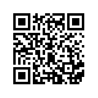
Learn more about safety features on Atlas Copco nutrunners and what measures the operator has to take for a safe operation. Click the link or scan the QR code below to view the video:
https://www.youtube.com/watch?v=FAh6yttvUpw
Country of Origin
For the Country of Origin, please refer to the information on the product label.
Dimensional Drawings
Dimensional Drawings can be found either in the Dimensional Drawings Archive, or on ServAid.
Please visit: http://webbox.atlascopco.com/webbox/dimdrw or https://servaid.atlascopco.com.
Overview
System Functionality
The tool comprises an embedded controller for configurations of tightening programs, batches and other tool functionality, such as input and output signals.
By connecting the tool to a PC via USB, or by setting up a wireless connection to the factory network, the embedded controller can be accessed through the IxB Software web user interface.
EHMI Module Description
The EHMI (Extended Human Machine Interface) module provides a tool-mounted interface for the operator, showing a subset of the IxB Software web user interface. It can be used to choose tightening programs and batch sequences, as well as display tightening results and progression within batch sequences.
The EHMI user interface consists of three push buttons and a graphical display. The buttons are used to navigate through the menus and to confirm selections.
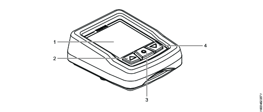
Position | Name | Description |
|---|---|---|
1 | Display | Screen displaying information to the user |
2 | Up button | Physical button for moving on-screen selection up. |
3 | Select button | Physical button for confirming an on-screen selection, as well as to navigate to the main menu (by pressing and holding for three seconds). |
4 | Down button | Physical button for moving on-screen selection down. |
The User Interface
Indicator Bar
The indicator bar is presented at the top of all menus. The icons in the indicator bar provides information on the elements listed below.
Icon | Description |
|---|---|
| The wireless connection icon indicates the signal strength of the tool's factory network connection. When no connection is established, the icon is crossed out. |
| The reverse ring icon indicates the position of the reverse ring on the tool, that is, the direction of rotation when the tool trigger is pushed. If the tool is disabled, the icon is crossed out. |
| The battery icon Indicates the charge status of the battery attached to the tool. |
The battery charge levels are listed below.
Battery Icon | Charge Level |
|---|---|
Full | |
Medium | |
| Low |
| Critically low |
| Tool is running on internal backup battery |
| No information available |
Main Menu
The main menu of the EHMI contains the following options:
Menu Item | Description |
|---|---|
| The Tightening menu shows a list of all the tightening programs available in the tool. |
| The Batch menu shows a list of all the batch sequences available in the tool. |
| The Tool menu provides information on the tool. |
| The Information menu provides information the EHMI itself. |
| The Network menu provides information on the factory network that the EHMI is connected to, as well as signal strength history. |
Tool Functionality
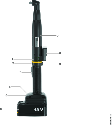
Position | Description |
|---|---|
1 | LED indicators |
2 | Reverse ring |
3 | Tool trigger |
4 | USB port |
5 | IAM (SD card) |
6 | Battery |
7 | Position for optional accessories |
8 | Display (EHMI) |
9 | Function button |
Product Power Source
This product can be used with either a battery, or with an electrical power cable in combination with a power supply unit.
Tool Key
The IxB tool naming format can be used to describe functions and features of the tool. Below is an example tool name with corresponding tool key.

Position | Description | Key |
|---|---|---|
1 | Platform | I = IxB (integrated controller) |
2 | Technology | T = Transducer |
3 | Powering | B = Battery |
4 | Tool shape | A = Angle P = Pistol S = Straight |
5 | Motor size | |
6 | Tool generation | |
7 | Max torque in Nm | |
8 | Output drive | I = Female hex HAD = Hold and Drive |
9 | Drive size | 06 = 1/4" 10 = 3/8" 13 = 1/2" |
10 | Accessories | HMI = EHMI |
11 | Accuracy | H = High torque accuracy |
Technical Product Data
Technical Product Data can be found on either ServAid, or the Atlas Copco website.
Please visit: https://servaid.atlascopco.com or www.atlascopco.com.
Accessories
Accessory Information
Visit the tool's product page on ServAid for information about compatible accessories.
LED Indicators
The LED ring of the tool is equipped with the following indicators:
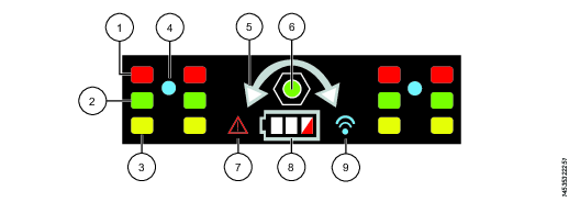
Position | LED indicator | Main indication |
|---|---|---|
1 | Red status LEDs | Tightening result, NOK |
2 | Green status LEDs | Tightening result, OK |
3 | Yellow status LEDs | Can be configured in the IxB Software to indicate different events |
4 | Blue LED | Can be configured in the IxB Software to indicate different events |
5 | Direction LEDs | Tightening direction |
6 | - | - |
7 | Alarm LED | Error has occurred in the tool |
8 | Battery LEDs | Battery charge status |
9 | Wireless connection LED | Connection established |
To configure the LED indicators, refer to IxB Software User Guide.
Installation
Installation Instructions
Connecting to the IxB Software Web User Interface
Attach the power source to the tool. The red and green LED indicators, together with the direction LED indicators are flashing, showing that the tool is starting up. Wait until the battery LED, and one of the direction LED indicators are lit. The tool is now ready to operate.
Remove the cover of the tool's USB port.
Connect the tool to the USB port of the PC. Open a web browser and type in the address of the IxB Software user interface: 169.254.1.1.
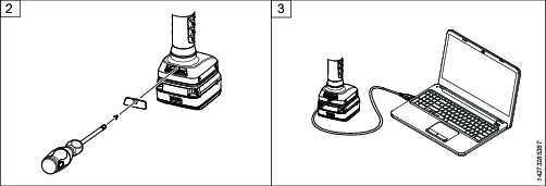
Battery LED do not light when PSU is connected.
Product Essentials Tutorials
https://www.youtube.com/watch?v=ffQHjRwbIgw
Attaching and Removing the Battery
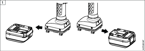
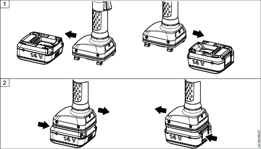
Attach the battery to the tool and make sure that it is fastened correctly. The battery can be attached pointing forward or backward to get the best accessibility and balance.
To remove the battery, press the button on the battery and push it out.
Installing Accessories
Disassembly of the tool and/or installations of accessories must only be performed by qualified maintenance personnel.
Required tools:
Adjustable spanner
Screwdriver
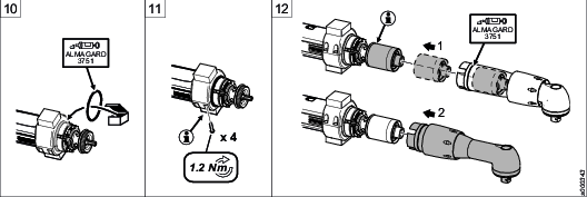
Put the front part in a clamping jaw of suitable size and fasten the clamping jaw in a vise.
Loosen the front cap nut using an adjustable spanner. Remove the tool from the vise.
Pull out the angle gear carefully from the tool.
Remove the following parts from the angle gear housing:
the lock ring (keep for later use)
the sealing washer (to be discarded)
the front cap nut (to be discarded)
Mount the following parts on the angle gear housing:
new applicable front cap nut. Apply a thin layer of grease on the inside of the cap nut.
new sealing washer
lock ring
Replace the O-ring on the motor housing with a thicker O-ring of the same diameter. Apply a thin layer of grease on the O-ring and on the lower section of the motor housing.
Place the tool into the half-ring with two pins on the inside. When the half-ring is placed in the correct position, the pins will fit into the slots of the motor housing and prevent the half-ring from turning.
Connect the flex cable to the bus port marked 1.
Connect the flex cable on the upper half-ring to the bus port marked 2 and put together the two half-rings.

If installing a laser scanner: do not stare into the beam. This device emits CDRH/IEC Class 2 laser and IEC Class 1M light.
Place an O-ring in the slot at the front of the half-rings. Apply a thin layer of grease on the O-ring.
Tighten the two half-rings with four screws using a screwdriver.

Make sure the sealing on the end of the half-rings seals tightly.
Pull out the planetary gear from the gear housing. Push down the planetary gear fully on the shaft.

Make sure the gear wheel is placed in correct position.
Put the gear back in position. Apply a thin layer of grease on the sealing washer.
Put the front part in the clamping jaw and fasten the clamping jaw in the vise.
Tighten the front cap nut using adjustable spanners.



Attaching the Electrical Power Cable
To attach the electrical power cable, see Product Instructions for Power Supply Unit 950.
Initial Configuration
EHMI Start-up Progress Indications
The information in this section is only valid for tools running IxB Software from version 3.7 and onwards.
When starting the tool, the EHMI will indicate if a software update is in progress by displaying the following messages:
Check for software update
Updating <module> App/Boot
Starting controller
A module is a subsystem or component which is part of the IxB tool, and updated through the IxB Software.
Module (as shown on the display) | Description |
|---|---|
MRT | Main board |
MCB | Power module |
FTS | Front transducer |
EHMI | Extended HMI |
BHMI | Basic HMI |
If an error occurs during the software update, the following message will be displayed:
Software update failed (errorId)
The errorId corresponds to error messages, as follows:
Id | Error Message | Description | Suggested Action |
|---|---|---|---|
0 | None | - | - |
1 | Module board info not valid | Module produced with incorrect data | Replace module |
2 | Module device information not valid | Module produced with incorrect data | Replace module |
3 | Module file corrupt | File system is corrupt | Replace IAM |
4 | Module firmware not compatible with hardware | Software not compatible with hardware | Update to later release |
5 | Module firmware file not found | File system is corrupt | Replace IAM |
6 | Error when reading module firmware file | File system is corrupt | Replace IAM |
7 | Communication timeout when trying to update module | Damage on the connector/cable or the module | Replace IAM |
8 | Error when receiving data from module | Damage on the connector/cable or the module | Service the tool |
9 | Unexpected reply from module | Damage on the connector/cable or the module | Service the tool |
10 | Module unreachable | Damage on the connector/cable or the module | Service the tool |
11 | Error when transmitting data to module | Damage on the connector/cable or the module | Service the tool |
12 | System on backup battery | System is running on backup battery | Restart tool - do not remove battery or power adapter until update is complete |
Software Installation and Upgrade
For information about software installation and upgrade, refer to IxB Software User Guide.
Tool Configuration
For information about establishing a wireless connection, installing licenses, configuring and assigning tightening programs, refer to IxB Software User Guide.
The link refers to the latest version of the software. User guides describing earlier versions of the software are available on ServAid.
Operation
Ergonomic Guidelines
Consider your workstation as you read through this list of general ergonomic guidelines to identify areas for improvement in posture, component placement, or work environment.
Take frequent breaks and change work positions frequently.
Adapt the workstation area to your needs and the work task.
Adjust for a convenient reach range by determining where parts and tools need to be located to avoid static load.
Use workstation equipment such as tables and chairs appropriate for the work task.
Avoid work positions above shoulder level or with static holding during assembly operations.
When working above shoulder level, reduce the load on the static muscles by lowering the weight of the tool, using for example torque arms, hose reels or weight balancers. You can also reduce the load on the static muscles by holding the tool close to the body.
Take frequent breaks.
Avoid extreme arm or wrist postures, particularly during operations requiring a degree of force.
Adjust for a convenient field of vision that requires minimal eye and head movements.
Use appropriate lighting for the work task.
Select the appropriate tool for the work task.
In noisy environments, use ear protection equipment.
Use high-quality inserted tools and consumables to minimize exposure to excessive levels of vibration.
Minimize exposure to reaction forces.
When cutting:
A cut-off wheel can get stuck if the cut-off wheel is bent or not guided properly. Use the correct flange for the cut-off wheel and avoid bending the cut-off wheel during operation.
When drilling:
The drill might stall when the drill bit breaks through. Use support handles if the stall torque is high. The safety standard ISO11148 part 3 recommends using a device to absorb a reaction torque above 10 Nm for pistol grip tools and 4 Nm for straight tools.
When using direct-driven screwdrivers or nutrunners:
Reaction forces depend on the tool settings and joint characteristics. Strength and posture determine the amount of reaction force that an operator can tolerate. Adapt the torque setting to the operator's strength and posture and use a torque arm or reaction bar if the torque is too high.
In dusty environments, use a dust extraction system or wear a mouth protection mask.
Operating Instructions
Tightening
Rotation Direction for the Tightening
Check that the tool is in the correct running direction by turning the reverse button or reverse ring.
Pistol Grip Models (with side buttons)
Press the reverse switch on the right hand side of the tool, to set the direction clockwise (CW).
Press the reverse switch on the left hand side of the tool, to set the direction counter-clockwise (CCW).
Pistol Grip Models (without side buttons)
Double press the function button on the top of the start trigger to shift the direction between clockwise (CW) and counter-clockwise (CCW).
Angle Models
Turn the reverse ring to the right, to set the direction clockwise (CW).
Turn the reverse ring to the left, to set the direction counter-clockwise (CCW).
Soft Start
The soft start function facilitates the screw head and thread to reach the snug level. The duration of the soft start is adjustable.
For further information about tightening, see Power Focus 6000 Configuration manual.
LED Indicator (HMI)
LED Indicator | Description |
|---|---|
Connection | Indicates the connection to the paired controller or software system. |
Batch | Indicates when the batch is done. |
Battery | Indicates battery status (flashing light = low battery, steady light = empty battery). |
Alarm | A failure or event is detected. |
EHMI Operations
Product Essentials Tutorials
https://www.youtube.com/watch?v=7UlLPb9hyrs
Enabling or Disabling the EHMI Select Button
The EHMI Select button can be enabled or disabled in the IxB Software web user interface, refer to IxB Software User Guide.
Events
Events in the system will generate event dialog boxes in the EHMI display, as well as in the IxB Software web user interface. To acknowledge events in the EHMI, press the Select button once.
Some events are not possible to acknowledge. They will show for three seconds before automatically disappearing from the display.
Tightenings
The EHMI can be used to select the tightening program for the tool. The selection of a tightening program made on the EHMI overrides whatever task was set for the tool in the IxB Software web user interface. Only tightening programs stored in the IxB Software of the tool can be selected from the EHMI.
Selecting a Tightening Program
If not in the main menu, press and hold the Select button until the main menu shows.
Press the Select button to open the Tightening menu.
Use the Up- and Down buttons to select a tightening program from the list. The number of the currently selected tightening program is marked white.
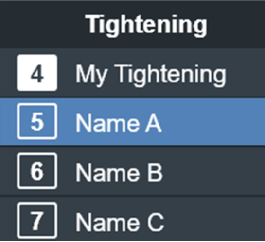
Press the Select button to confirm.
Reading a Tightening Result
The tightening result is presented graphically with a result gauge. The gauge is divided into three parts indicating either an OK or NOK tightening. Field colors (red for NOK, green for OK) are only shown at tightening result.
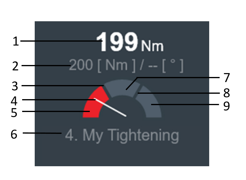
Position | Name | Description |
|---|---|---|
1 | Final torque or final angle | Torque/angle when tightening program has concluded. |
2 | Target torque or target angle | Torque/angle which was aimed for. |
3 | Min limit | Indicates lower limit of OK tightening (min angle or min torque) |
4 | Indicator | Gauge indicator showing the result on the scale |
5 | Low field | Indicates NOK tightening due to low angle/torque |
6 | Tightening program | Sequence number and name of the tightening program used |
7 | OK field | Indicates an OK tightening |
8 | Max limit | Indicates upper limit of OK tightening (max angle or max torque) |
9 | Hi field | Indicates NOK tightening due to high angle/torque |
Batch
Batch sequences are used when operators need to perform a series of tightenings in a single job, and can be restricted to only follow a specific order in which the tightenings are performed. Batch sequences consist of one or more batches, and each batch consists of one or more tightenings.
The EHMI can be used to select the batch sequence for the tool. The selection of a batch sequence made on the EHMI overrides whatever task was set for the tool in the IxB Software web user interface.
Selecting a Batch Sequence
If not in the main menu, press and hold the Select button until the main menu shows.
Use the Down button to cycle through the main menu items to the Batch menu.
Press the Select button to open the Batch menu.
Use the Up- and Down buttons to select the batch sequence from the list.
Press the Select button to confirm.
Selecting a Batch Control Option
The EHMI can be used to control the progression of the batch sequence.
While in a batch sequence, press the Select button.
Use the Up- and Down buttons to select batch control option.
Option
Description
Abort sequence
Aborts the entire sequence. Starts new batch sequence if parameter Lock tool on batch sequence complete is set to Off.
Batch bypass
Aborts the current batch and starts the next batch in the sequence. Unfinished tightenings in the skipped batch are set to NOK.
Batch reset
Resets the batch; starts again at the first tightening in the batch.
Batch decrement
Returns to the previous tightening in the batch.
Batch increment
Skips the current tightening, and moves to the next tightening in the batch. The skipped tightening is set to NOK.
Press the Select button to confirm.
Depending on the batch sequence parameters, the tool will lock when certain actions are accessed on the EHMI. For example, when the parameter Lock tool on batch sequence complete is set to On, the tool will lock when the batch sequence is aborted.
Reading a Batch Result
The result view will display two rows of indicators, with the top row representing the number of batches in the batch sequence, and the bottom row representing the tightenings in a batch.
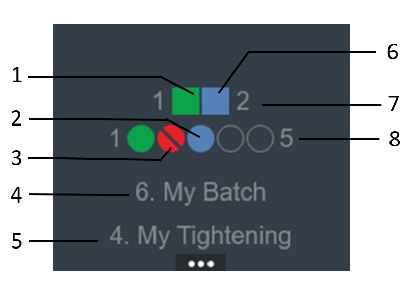
Position | Description |
|---|---|
1 | Batch completed OK |
2 | Tightening in progress |
3 | NOK tightening |
4 | Name of the currently active tightening program |
5 | Name of the currently active batch |
6 | Batch in progress |
7 | Number of batches in the batch sequence |
8 | Number of tightenings in the batch currently in progress |
Viewing Tool Information
If not in the main menu, press and hold the Select button until the main menu shows.
Use the Up- and Down buttons to cycle through the main menu items to the Tool menu.
Press the Select button to open the Tool menu.
Use the Up- and Down buttons to view the tool information.
The Tool menu provides the following information:
Tool Information | Description |
|---|---|
Serial no | Tool serial number |
Software version | Software version installed on the tool |
Model | Tool model designation |
Production date | Date when the tool was manufactured |
Ordering number | Product number for ordering the tool |
Max torque | Tool's maximum torque |
Max speed | Tool's maximum speed |
Gear ratio | Gear ratio of the tool shaft |
Remaining tightenings | Approximate number of tightenings left before service of the tool is required |
Service date | Date of the last service performed on the tool |
Calibration date | Date the tool was last calibrated |
Next calibration date | Date when the tool should be calibrated next |
Viewing EHMI Information
If not in the main menu, press and hold the Select button until the main menu shows.
Use the Up- and Down buttons to cycle through the main menu items to the Infomation menu.
Press the Select button to open the Information menu.
Use the Up- and Down buttons to view the EHMI information.
The Information menu provides the following data on the EHMI.
EHMI Information | Description |
|---|---|
Software version | EHMI software installed and date of installation |
Build date | Date when the EHMI software was built |
Boot-code version | Version number of the boot-code |
Updater version | Version number of the updater used |
Board variant | Variant of the installed circuit board |
Hardware rev. no | Revision number of the installed circuit board |
Board serial number | Circuit board serial number |
Language | Display language |
Viewing Network Information
If not in the main menu, press and hold the Select button until the main menu shows.
Use the Up- and Down buttons to cycle through the main menu items to the Network menu.
Press the Select button to open the Network menu.
Press the Select button again to open the Information menu.
Use the Up- and Down buttons to view the network information.
The Network menu provides the following information about the network that the tool is connected to:
Network Information | Description |
|---|---|
Radio type | Type of radio (WLAN) |
Configuration mode | Type of connection (DHCP) |
IP address | IP address of the tool |
Subnet mask | IP address subnet mask |
Gateway | Connection gateway |
Primary DNS server | Primary DNS server address |
Secondary DNS server | Secondary DNS server address |
Domain name | Domain name (can be empty) |
Host name | Host name (tool) |
Channel list | Available Wifi channels that can be selected |
Active channel | Channel currently in use |
If not in the main menu, press and hold the Select button until the main menu shows.
Use the Up- and Down buttons to cycle through the main menu items to the Network menu.
Press the Select button to open the Network menu.
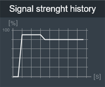
Press the Down button to reach the Signal strength history option, and press the Select button. The graph can be used to detect potential connection blind spots for the tool on a production line.
Battery Charge LED Indicator
The tool is powered by a Lithium-ion battery. The battery capacity is dependent on the battery model and the type of work performed with the tool.
The battery LED indicator on the tool indicates the battery's State of Charge (SOC). It is shown by three bars indicating the remaining capacity, as follows:
Battery charge indicator | Remark |
|---|---|
3 white bars | Full charge. |
2 white bars | High charge. |
1 white bar | Medium charge. |
1 red bar | Low charge. |
1 red bar, flashing | Critical level, not possible to perform tightening. Charge battery |
All bars flashing white | Tool is running on the backup battery. |
For information about the battery charge and health indicator located on the battery itself, refer to the Product Instructions for the battery model in question.
Product Essentials Tutorials
https://www.youtube.com/watch?v=vIzJvQ__ZEc
Tool Calibration
For information on calibration of this tool, refer to IxB Software User Guide.
The link refers to the latest version of the software. User guides describing earlier versions of the software are available on ServAid.
Tightening
As the tightening torque increases, the reaction force builds up equally. Make sure that the tool is in correct working order and correctly programmed. Unexpected behavior from the tool may result in operator injury.
Rotation Direction for the Tightening
Check that the tool is in the correct running direction by:
Turning the reverse ring to the right to set the tightening direction to clockwise (CW).
Turning the reverse ring to the left to set the tightening direction to counterclockwise (CCW).
LED Indicator Flash Patterns
The standard flash patterns of the tool's LED indicators are shown below. To configure the LED indicators, refer to IxB Software User Guide.
LED indicator | Light behavior | Status |
|---|---|---|
Tightening direction Red and green | Both directions steady Flashing | Tool is starting up. |
Battery and | Steady | Tool has started and is ready to operate. |
Tightening direction | Both directions flashing | Tool is starting up after software update. |
Tightening direction | Both directions flashing eight times, followed by steady light for half a second. | Indicates one of the following:
For more information on error messages, refer to IxB Software User Guide. |
Tightening Program Selection Indication
The indicators in the LED ring can be configured to show the currently selected tightening program in a sequence (1−9). The function must be activated in the IxB Software web user interface.
To show the currently selected program in a sequence, turn the reverse ring to the left. The LED of the tightening program is displayed from left to right and top to bottom, as shown below. If the currently selected tightening program has a position in the sequence which is greater than nine, no LED indicator will be lit.
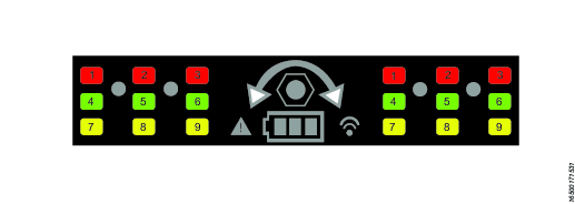
Turn the reverse ring to the right and push the tool trigger to run the tightening program. The result is displayed on the LED ring.
To show the selected program again, turn the reverse ring to the left.
The result for a loosening will be displayed as normal. If the reverse ring is turned to the right after a completed loosening then the selected tightening program will be shown on the LED ring.
Dual Trigger
Dual trigger (Recommended to use during operation)
Service
Preventing ESD Problems
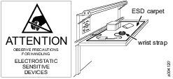
The components inside the product and controller are sensitive to electrostatic discharge. To avoid future malfunction, make sure that service and maintenance is carried out in an ESD approved work environment. The figure below shows an example of an appropriate service work station.
Transferring Configurations with IAM
The Intelligent Application Module (IAM) has the form factor of an SD card. The card contains all the current network configurations and settings.
In case of a tool failure, the card can be transferred to a new tool and all functionality remains the same. When the card is transferred, the new tool will be updated to the software on the card. It is good practice to make sure the new tool is already running the same software version as the old tool, to minimize the risk of data loss.
Note that the saved results associated with the tool will be lost when the card is transferred to another tool. The MAC-address is associated with the card, not with the tool itself. When transferring a card to a new tool, the tool's MAC-address will therefore be updated.
IAM can not be used for anything but storing the tool configuration data and software. Reformatting the card, as well as manipulating the data on the card through other means than IxB Software or ToolsTalk Service 2, will result in an unusable card.
Product Essentials Tutorials
https://www.youtube.com/watch?v=zB0QcQSdsz8
Maintenance Instructions
Overhaul
Have the tool serviced by a qualified repair person using only identical replacement parts. This will ensure that the safety of the tool is maintained. Service must only be carried out by qualified personnel who have been trained for service on IxB tools.
The electric motor is a sealed unit and may under no circumstances be opened by anyone else than Atlas Copco Industrial Technique AB. If it is judged that the electric motor is defect or in need of service, the complete motor unit should be returned to Atlas Copco Industrial Technique AB for exchange. Motors which have been opened by anyone else than Atlas Copco Industrial Technique AB will not be serviced.
Overhaul and preventive maintenance is recommended at regular intervals once per year or after maximum 250.000 tightenings, depending on which occurs sooner. More frequent overhaul may be needed if the machine is used in heavy-duty operations. If the machine is not working properly, it should immediately be taken out of service for inspection.
When dismantling the tool always use the specially designed service tool(s) recommended in the Spare Parts section on ServAid - https://servaid.atlascopco.com.
Service Recommendations
Preventive maintenance is recommended at regular intervals. See the detailed information on preventive maintenance. If the product is not working properly, take it out of service and inspect it.
If no detailed information about preventive maintenance is included, follow these general guidelines:
Clean appropriate parts accurately
Replace any defective or worn parts
Preventive Maintenance
Maximizing Battery Life
Do not leave the battery connected to the tool if you do not use the tool for several days. The battery can discharge and go into “sleep mode” which will require a special wake-up charge procedure. For further information, see instructions for multicharger, 4211542485.
Backup Battery Maintenance
The tool includes an internal backup battery. The backup battery is used, for example, to keep the radio communication active during exchange of the main battery. The backup battery gives approximately 20 seconds to exchange the main battery, before the tool shuts down.
Always connect a newly manufactured tool to a main battery and power it up for two hours to charge the backup battery.
When using software versions prior to the versions listed in below table, replace the backup battery at least every 12 months. The replacement procedure must be carried out by a qualified service technician. A replaced backup battery is to be recycled according to the Recycling Instruction.
With software releases according to below table, replace the backup battery every third year. The increased service interval applies to a fresh battery used only together with the software versions in below table. If the backup battery already is close to 12 months old, it is recommended to replace the backup battery when updating to the new software.
TBP/TBP-S | SRB31 | SRB81 | IxB |
Version 2.1.3 or later | Version 1.3.15 or later | Version 1.4.0 or later | Version 3.10.4 or later |
Storage Conditions
The backup battery lifetime is negatively affected by extreme temperatures. Store the tool in an environment with an ambient temperature between 0 - 30 °C. Do not keep spare backup batteries in storage.
If a newly manufactured tool is to be kept in storage, make sure to power it up for at least two hours before putting it in storage.
While in storage, make sure to power on the tool at least every five months to recharge the backup battery. The tool must be powered on for at least two hours each time.
Lubrication Instructions
Lubricant Guide
Part | Lubricant |
|---|---|
Planetary gears with bearings | Molycote BR2 Plus |
Angle gears with bearings | Atlas Gear Grease 270 (Tools configured with 110° angle head (-SZ), may also use Molycote Longterm 2 plus.) |
Threads, O-rings, other | Almagard LE 3751 |
Lubrication
Lubricate according to the Lubrication Guide at each service occasion.
For more information, see Spare Parts section in ServAid - https://servaid.atlascopco.com.
Upgrading EHMI Software
The software installed on the EHMI can be updated using a USB storage device.
Upgrade Requirements
USB storage device
Cable with female USB type-A on one end, and male Micro-B on the other end (alternatively, a USB device with 2 connectors, male type-A and male micro-B, can also be used)
Version number of the currently installed EHMI firmware. To view the version number, go to Information in the main menu and select Software version.
In a web browser, go to the Marketing & Support Portal > Software Center > Accessories. Download the updated software (application and/or GUI data) in the category EHMI.

Some application updates require also the GUI data to be updated. If the version of the GUI data is incorrect an error message will be displayed at restart. The GUI data will never require update as long as the application is not updated.
Filename
Software type
Description
eHMI_STR_x.x.x.fbk
Application software STR EHMI and ITB EHMI
This is usually the only software that needs to be updated for the tool.
guidata-x.x.x.fbk
GUIDATA
Graphic data for all characters. Usually does not require upgrading.
Store the downloaded files on the root of the empty USB storage device.
Enter the EHMI update menu, using one of methods described below.
Method 1
Disconnect the battery from the tool and wait for the backup battery to discharge.
Press and hold the Select button while attaching the battery again. Continue to hold the Select button until the Update menu is shown.
Method 2
Navigate to the Information menu.
Press and hold the Down button, while pressing the Up button twice to enter the hidden submenu.
In the submenu, navigate to Reset, and press and hold the Select button until the Update menu is shown.
Using a 5 mm Allen key, remove the lid covering the USB port on the EHMI. Connect the USB storage device to the EHMI USB port.
Using the Up- and Down buttons, navigate to the update file, and press the Select button to start the update process.
When updating is complete, press the Up button to reboot the system.
Troubleshooting
Events and Error Codes
For a full list of tool event and error codes, refer to IxB Software User Guide.
Overheated Tool
The tool can handle any normal line jobs that an operator sustains with the proper adjustments.
The tool temperature can be influenced by the following parameters:
short cycle time
torque above rated
too low speed
very high prevailing torque
very soft joints
ambient temperature
Recycling
Environmental Regulations
When a product has served its purpose it has to be recycled properly. Dismantle the product and recycle the components in accordance with local legislation.
Batteries shall be taken care of by your national battery recovery organization.
Recycling Instruction
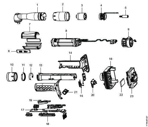
Position | Part | Remarks | Recycle as |
|---|---|---|---|
1 | Angle head |
| Metal, Steel |
2 | Cap nut | Metal, Steel | |
3 | Planetary gear | Metal, Steel | |
4 | Torque transducer | Electronics (WEEE) | |
5 | Shaft | Metal, Steel | |
6 | Plate | 2 pcs | Metal, Steel |
7 | Cover | 2 pcs | Plastic, Other, PA |
8 | Motor | Electronics (WEEE) | |
9 | HMI module | Electronics (WEEE) | |
10 | Cap nut | Metal, Steel | |
11 | Snap ring | Metal, Steel | |
12 | Lock ring | Metal, Steel | |
13 | Handle body | Metal, Aluminum | |
14 | Handle | 2 pcs | Plastic, Other, PA |
15 | Antenna | 2 pcs | Electronics (WEEE) |
16 | Battery holder | Metal, Aluminum | |
17 | Main board module | Electronics (WEEE) | |
18 | Main board holder | 4 pcs | Rubber, Thermoplastic elastomer |
19 | Button | Metal, Steel | |
20 | Plastic holder | 2 pcs | Plastic. Other, POM |
21 | Lid | Plastic, Other, PA | |
22 | Back-up battery | Battery, Li-ion | |
23 | Power module | Electronics (WEEE) |

