Product Information
General Information
Safety Signal Words
The safety signal words Danger, Warning, Caution, and Notice have the following meanings:
DANGER | DANGER indicates a hazardous situation which, if not avoided, will result in death or serious injury. |
WARNING | WARNING indicates a hazardous situation which, if not avoided, could result in death or serious injury. |
CAUTION | CAUTION, used with the safety alert symbol, indicates a hazardous situation which, if not avoided, could result in minor or moderate injury. |
NOTICE | NOTICE is used to address practices not related to personal injury. |
Warranty
Product warranty will expire 12 months after the product is first taken into use, but will in any case expire at the latest 13 months after delivery.
Normal wear and tear on parts is not included within the warranty.
Normal wear and tear is that which requires a part change or other adjustment/overhaul during standard tools maintenance typical for that period (expressed in time, operation hours or otherwise).
The product warranty relies on the correct use, maintenance, and repair of the tool and its component parts.
Damage to parts that occurs as a result of inadequate maintenance or performed by parties other than Atlas Copco or their Certified Service Partners during the warranty period is not covered by the warranty.
To avoid damage or destruction of tool parts, service the tool according to the recommended maintenance schedules and follow the correct instructions.
Warranty repairs are only performed in Atlas Copco workshops or by Certified Service Partners.
Atlas Copco offers extended warranty and state of the art preventive maintenance through its ToolCover contracts. For further information contact your local Service representative.
For electrical motors:
Warranty will only apply when the electric motor has not been opened.
ServAid
ServAid is a portal that is continuously updated and contains Technical Information, such as:
Regulatory and Safety Information
Technical Data
Installation, Operation and Service Instructions
Spare Parts Lists
Accessories
Dimensional Drawings
Please visit: https://servaid.atlascopco.com.
For further Technical Information, please contact your local Atlas Copco representative.
Safety Data Sheets MSDS/SDS
The Safety Data Sheets describe the chemical products sold by Atlas Copco.
Please consult the Atlas Copco website for more information www.atlascopco.com/sds.
Product Safety Video for Nutrunners
Learn more about safety features on Atlas Copco nutrunners and what measures the operator has to take for a safe operation. Click the link or scan the QR code below to view the video:
https://www.youtube.com/watch?v=FAh6yttvUpw

Installation of Vibrating Tools
We recommend using a minimum length of 300 mm (12") of flexible hose for compressed air between a vibrating tool and the quick-action coupling.
Signs and Stickers
The product is fitted with signs and stickers containing important information about personal safety and product maintenance. The signs and stickers shall always be easy to read. New signs and stickers can be ordered by using the spare parts list.

Country of Origin
For the Country of Origin, please refer to the information on the product label.
Dimensional Drawings
Dimensional Drawings can be found either in the Dimensional Drawings Archive, or on ServAid.
Please visit: http://webbox.atlascopco.com/webbox/dimdrw or https://servaid.atlascopco.com.
Overview
Technical Product Data
Technical Product Data can be found on either ServAid, or the Atlas Copco website.
Please visit: https://servaid.atlascopco.com or www.atlascopco.com.
Accessories
Reporting, RE – signal
Reporting (RE) machines supply an air signal that can be connected to a monitoring instrument that counts the number of approved tightening and detects premature shut-off and rehits and other irregularities.
Service Overview
Service Recommendations
Preventive maintenance is recommended at regular intervals. See the detailed information on preventive maintenance. If the product is not working properly, take it out of service and inspect it.
If no detailed information about preventive maintenance is included, follow these general guidelines:
Clean appropriate parts accurately
Replace any defective or worn parts
Preventive maintenance
Overhaul and preventive maintenance is recommended at regular intervals once per year or after maximum 250.000 tightening depending on which occurs sooner. More frequent overhaul may be needed, if used at high torque and long tightening times.
Installation
Installation Requirements
Air Quality
For optimum performance and maximum product life we recommend the use of compressed air with a maximum dew point of +10°C (50°F). We also recommend to install an Atlas Copco refrigeration type air dryer.
Use a separate air filter which removes solid particles larger than 30 microns and more than 90% of liquid water. Install the filter as close as possible to the product and prior to any other air preparation units to avoid pressure drop.
For impulse/impact tools make sure to use lubricators adjusted for these tools. Regular lubricators will add too much oil and therefore decrease the tool performance due to too much oil in the motor.
Make sure that the hose and couplings are clean and free from dust before connecting to the tool.
Both lubricated and lubrication free products will benefit from a small quantity of oil supplied from a lubricator.
Air Lubrication Guide
Brand | Air lubrication |
|---|---|
Atlas Copco | Optimizer (1 liter) 9090 0000 04 |
Q8 | Chopin 46 |
Shell | Shell Air Tool Oil S2 A 320 |
Compressed Air Connection
For correct air pressure and hose size, see the Technical Product Data on - https://servaid.atlascopco.com or www.atlascopco.com.
Make sure that the hose and couplings are clean and free from dust before connecting to the tool.
Operation
Ergonomic Guidelines
Consider your workstation as you read through this list of general ergonomic guidelines to identify areas for improvement in posture, component placement, or work environment.
Take frequent breaks and change work positions frequently.
Adapt the workstation area to your needs and the work task.
Adjust for a convenient reach range by determining where parts and tools need to be located to avoid static load.
Use workstation equipment such as tables and chairs appropriate for the work task.
Avoid work positions above shoulder level or with static holding during assembly operations.
When working above shoulder level, reduce the load on the static muscles by lowering the weight of the tool, using for example torque arms, hose reels or weight balancers. You can also reduce the load on the static muscles by holding the tool close to the body.
Take frequent breaks.
Avoid extreme arm or wrist postures, particularly during operations requiring a degree of force.
Adjust for a convenient field of vision that requires minimal eye and head movements.
Use appropriate lighting for the work task.
Select the appropriate tool for the work task.
In noisy environments, use ear protection equipment.
Use high-quality inserted tools and consumables to minimize exposure to excessive levels of vibration.
Minimize exposure to reaction forces.
When cutting:
A cut-off wheel can get stuck if the cut-off wheel is bent or not guided properly. Use the correct flange for the cut-off wheel and avoid bending the cut-off wheel during operation.
When drilling:
The drill might stall when the drill bit breaks through. Use support handles if the stall torque is high. The safety standard ISO11148 part 3 recommends using a device to absorb a reaction torque above 10 Nm for pistol grip tools and 4 Nm for straight tools.
When using direct-driven screwdrivers or nutrunners:
Reaction forces depend on the tool settings and joint characteristics. Strength and posture determine the amount of reaction force that an operator can tolerate. Adapt the torque setting to the operator's strength and posture and use a torque arm or reaction bar if the torque is too high.
In dusty environments, use a dust extraction system or wear a mouth protection mask.
Operating Instructions
Air Pressure Monitoring, RE-Signal S1
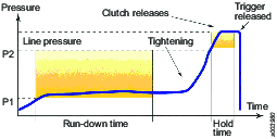
Reporting pneumatic assembly tools provide a pneumatic signal that indicates which part of the tightening cycle the tool has reached, by means of variations in air pressure.
In the RE-Controller box timers are triggered when certain pressure levels are reached.
Pressure level 1 (P1) starts a timer that checks that the tightening cycle is not too short.
Pressure level 2 (P2) starts a timer that checks the time taken from when the clutch has been released to when the operator releases the trigger to ensure that it is not too short.
The controller measures the differential pressure over the motor.
It should be noted that the system does not measure torque! Regular check of installed torque/torque output of the tool must be done separately.
The RE-Controller checks the air-line pressure. One of the most common problems in air-line systems is pressure variations. If the pressure drops too much the tool might stall and/or the torque will not be correct. The RE-Controller will give a signal if the pressure drops too much.
The RE-Controller alerts the operator when it detects:
Missed fasteners
Premature tool shut-off
Stripped threads
Cross-threading
Rehits
Drop in air supply
The air pressure inside the tool is measured through a small hose (see Optional accessories - Kit RE-Signal) and converted into a digital signal. This signal is processed in the RE-Controller. The RE-Controller gives instant visual and audio feedback to the operator on whether the tightening was OK or not OK.
For further information, please see leaflet 9833 1358 01.
Tightening Torque
For accurate operation and safety, the tightening torque of the nut runner must be set correctly in relation to the screw joint. Check the tightening torque given to the joint in question.
The tightening torque is adjusted by altering the tension of the clutch spring. Turn the protection ring until the hole in the clutch housing is free. Then turn the out going spindle until you can see the keyhole in the adjustment washer. Turn the adjustment key clockwise to decrease and anticlockwise to increase the torque. After the adjustment, turn the protective ring back again.
Verification of Tightening Torque
Recommended equipment for verification if tightening torque are an Atlas Copco Torque Analyser plus an appropriately-sized transducer together with the available test joints.
Service
Maintenance Instructions
Service Recommendations
Preventive maintenance is recommended at regular intervals. See the detailed information on preventive maintenance. If the product is not working properly, take it out of service and inspect it.
If no detailed information about preventive maintenance is included, follow these general guidelines:
Clean appropriate parts accurately
Replace any defective or worn parts
Preventive Maintenance
Preventive maintenance
Overhaul and preventive maintenance is recommended at regular intervals once per year or after maximum 250.000 tightening depending on which occurs sooner. More frequent overhaul may be needed, if used at high torque and long tightening times.
Testing of tightening torque
Torque and angle testing instrument
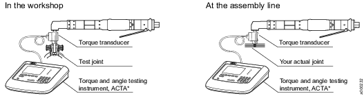
ACTA* 3000/ 4000. For further informatiom, please see our main catalogue or separate leaflet.
Testjoint and Transducer
Select testjoint and transducers according to maximum torque of your tool
Soft joints

Bolt size | Torque range Nm | Ordering No. | Torque rate Nm/rev. | Degrees at rated capacity | Service kit* |
|---|---|---|---|---|---|
M8 | 15 | 4080 0788 91 | 10 | 540 | 4080 0788 80 |
M10 | 30 | 4080 0789 91 | 24 | 450 | 4080 0789 80 |
M12 | 60 | 4080 0790 91 | 40 | 540 | 4080 0790 80 |
M14 | 90 | 4080 0791 91 | 60 | 540 | 4080 0791 80 |
M16 | 200 | 4080 0866 90 | 200 | 360 | 4080 0865 80 |
M20 | 400 | 4080 0868 90 | 400 | 360 | 4080 0867 80 |
M30 | 800 | 4080 0876 92 | 800 | 360 | 4080 0867 80 |
* Including 2x bolts, 2x nuts, 2x washers
In-line torque transducers – Torque models
Model | Drive Hex inch | Drive Square inch | Rated capacity Nm | ft lb | Ordering No |
|---|---|---|---|---|---|
IRTT 5-I06 | ¼ |
| 5 | 4 | 8092 1129 05 |
IRTT 20-I06 | ¼ |
| 20 | 15 | 8092 1129 10 |
IRTT 20-06 |
| ¼ | 20 | 15 | 8092 1129 15 |
IRTT 25-10 |
| 3/8 | 25 | 18 | 8092 1129 20 |
IRTT 75-10 |
| 3/8 | 75 | 55 | 8092 1129 25 |
IRTT 180-13 |
| ½ | 180 | 133 | 8092 1129 30 |
IRTT 500-20 |
| ¾ | 500 | 369 | 8092 1129 35 |
IRTT 750-25 |
| 1 | 750 | 553 | 8092 1129 40 |
IRTT 1400-25 |
| 1 | 1400 | 1033 | 8092 1129 45 |
In-line torque transducers – Torque/angle models
Model | Drive Hex inch | Drive Square inch | Rated capacity Nm | ft lb | Ordering No |
|---|---|---|---|---|---|
IRTT 2A-I06 | ½ |
| 2 | 1.5 | 8092 1130 01 |
IRTT 5A-I06 | ¼ |
| 5 | 4 | 8092 1130 06 |
IRTT 20A-I06 | ¼ |
| 20 | 15 | 8092 1130 11 |
IRTT 20A-06 |
| ¼ | 20 | 15 | 8092 1130 16 |
IRTT 25A-10 |
| 3/8 | 25 | 18 | 8092 1130 21 |
IRTT 75A-10 |
| 3/8 | 75 | 55 | 8092 1130 26 |
IRTT 180A-13 |
| ½ | 180 | 133 | 8092 1130 31 |
IRTT 500A-20 |
| ¾ | 500 | 369 | 8092 1130 36 |
IRTT 750A-25 |
| 1 | 750 | 553 | 8092 1130 41 |
IRTT 1400A-25 |
| 1 | 1400 | 1033 | 8092 1130 46 |
IRTT 3000A-38 |
| 1½ | 3000 | 3000 | 8092 1130 51 |
Service instructions
Service instructions
Overhaul and preventive maintenance is recommended at regular intervals once per year or after maximum 250.000 tightening depending on which occurs sooner. More frequent overhaul may be needed, if used at high torque and long tightening times. If the machine is not working properly, it should immediately be taken away for inspection.
The strainer at the air inlet and the exhaust silencer should be cleaned frequently or replaced in order to prevent clogging, which decreases the capacity.
At the overhauls, all parts should be cleaned accurately and defective or worn parts (i.e. O-rings, vanes) should be replaced.
Cleaning
Clean all parts thoroughly in white spirit or similar cleaning agent. To prevent clogging and decreased power, it could be necessary to clean the strainer (if used) and the exhaust filter between the overhauls.
Inspection
After the cleaning, inspect all parts. Damaged and worn parts should be replaced.
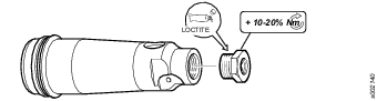
Tightening of Threaded Connections
The tightening torques indicated in the exploded views list in ServAid (see Spare parts section in https://servaid.atlascopco.com) are established to achieve the correct clamping force and prevent the parts from coming loose.
When servicing these parts, they must be able to open up without being destroyed. In special circumstances (depending on application and usage) the parts may however come loose after some time of operation. In such cases the torque can be increased by 10-20%. If necessary, a low or medium threadlocking fluid can also be applied.
Example
Lubrication Instructions
Rust Protection and Cleaning
Water in the compressed air can cause rust. To prevent rust we strongly recommend to install an air dryer.
Water and particles can cause sticking of vanes and valves. This can be prevented by installing an air filter close to the product to avoid pressure drop.
Before longer stand stills always protect your tool by adding a few drops of oil into the air inlet. Run the tool for 5–10 seconds and absorb any access oil at the air outlet in a cloth.
Lubrication Guide
|
Brand |
General purpose, Bearings and Gears* |
|---|---|
|
BP |
Energrease LS-EP2 |
|
Castrol |
OBEEn UF 1 |
|
Esso |
Beacon EP2 |
|
Q8 |
Rembrandt EP2 |
|
Mobil |
Mobilegrease XHP 222 NLG 2 |
|
Klüber Lub. |
Klübersynth UH 1 14-151 |
|
Texaco |
Multifak EP2 |
|
Molykote |
BR2 Plus |
* Not for angle gears.
|
Brand |
Angle gears |
|---|---|
|
Molykote |
Longterm 2 Plus |
Lubrication of motor parts
No grease is needed for protected Ball bearings.
Apply a thin layer of oil where needed.
For Maximum Performance
At tough working conditions – soft joints and max. setting – lubrication of the air is recommended.
With extreme dry air the service life of vanes and machine performance might be reduced. A daily supply of 0.1 – 0.2 ml oil into the machine inlet will improve the machine performance. Alternatively consider an automatic lubricator device, Atlas Copco oil fog lubricator DIM, or single point lubricator DOS, which will improve the machine performance.
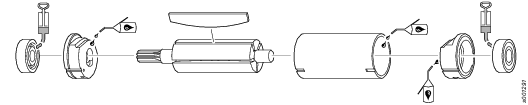
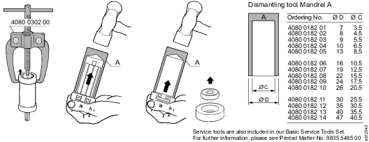
Dismantling/Assembling Instructions
Dismantling of Motor
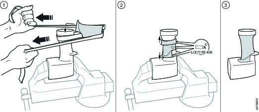
Assembly
Remove silencer and air nipple. Then completely remove the old Rubber cover. Fix the Motor casing in a vice. To easy the assembly put some soap-water mixture on the new Rubber cover ends. Make a loop of a heawy duty strap and then put the loop of strap through the Rubber cover and then around the Handle, see illustration 1 below. Pull on strap until Rubber cover is completely over the lower part of handle.
Gluing
When cover is in correct position clean the ends of cover from soap. Then carefully apply glue (Loctite 406) on the inside around edges and in the middle of cover, see illustration 2 below. It is especially important that the surface near the trigger is carefully coated with glue. Press Rubber cover so it fits nice and thight, see illustration 3 below.
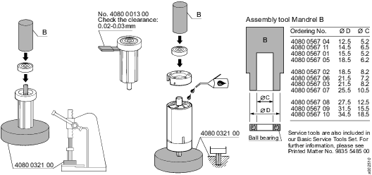
Assembly of Motor
Recycling
Environmental Regulations
When a product has served its purpose it has to be recycled properly. Dismantle the product and recycle the components in accordance with local legislation.
Batteries shall be taken care of by your national battery recovery organization.