SML-T-POSI2
Torque Arm
Product Information
General Information
Safety Signal Words
The safety signal words Danger, Warning, Caution, and Notice have the following meanings:
DANGER | DANGER indicates a hazardous situation which, if not avoided, will result in death or serious injury. |
WARNING | WARNING indicates a hazardous situation which, if not avoided, could result in death or serious injury. |
CAUTION | CAUTION, used with the safety alert symbol, indicates a hazardous situation which, if not avoided, could result in minor or moderate injury. |
NOTICE | NOTICE is used to address practices not related to personal injury. |
Warranty
Product warranty will expire 12+1 months after dispatch from Atlas Copco's Distribution Center.
Normal wear and tear on parts is not included within the warranty.
Normal wear and tear is that which requires a part change or other adjustment/overhaul during standard tools maintenance typical for that period (expressed in time, operation hours or otherwise).
The product warranty relies on the correct use, maintenance, and repair of the tool and its component parts.
Damage to parts that occurs as a result of inadequate maintenance or performed by parties other than Atlas Copco or their Certified Service Partners during the warranty period is not covered by the warranty.
To avoid damage or destruction of tool parts, service the tool according to the recommended maintenance schedules and follow the correct instructions.
Warranty repairs are only performed in Atlas Copco workshops or by Certified Service Partners.
Atlas Copco offers extended warranty and state of the art preventive maintenance through its ToolCover contracts. For further information contact your local Service representative.
Website
Information concerning our Products, Accessories, Spare Parts and Published Matters can be found on the Atlas Copco website.
Please visit: www.atlascopco.com.
ServAid
ServAid is a portal that is continuously updated and contains Technical Information, such as:
Regulatory and Safety Information
Technical Data
Installation, Operation and Service Instructions
Spare Parts Lists
Accessories
Dimensional Drawings
Please visit: https://servaid.atlascopco.com.
For further Technical Information, please contact your local Atlas Copco representative.
Safety Data Sheets MSDS/SDS
The Safety Data Sheets describe the chemical products sold by Atlas Copco.
Please consult the Atlas Copco website for more information www.atlascopco.com/sds.
Country of Origin
For the Country of Origin, please refer to the information on the product label.
Dimensional Drawings
Dimensional Drawings can be found either in the Dimensional Drawings Archive, or on ServAid.
Please visit: http://webbox.atlascopco.com/webbox/dimdrw or https://servaid.atlascopco.com.
Overview
General properties
Atlas Copco torque arms are an excellent means of assistance when using electric or pneumatic screwdrivers and nutrunners. They stress relieve the operators arm, wrist and shoulder from vibration, torque and weight during repeated actions. Even at a modest level of exertion repeated actions can lead to severe disorders. As an additional advantage the Atlas Copco torque arms also make savings on the tool accessories e.g.bits, taps etc. due to entering the screw or the hole more in right angle.
Torque arms in the SMS series have a large working range and are exceptionally easy to position and handle. The design is intended for heavy duty operations over a long period of time.Tool torque should not exceed the specified torque range of each specific arm.
Technical Product Data
Technical Product Data can be found on either ServAid, or the Atlas Copco website.
Please visit: https://servaid.atlascopco.com or www.atlascopco.com.
Installation
Installation Instructions
Installing the digital top encoder
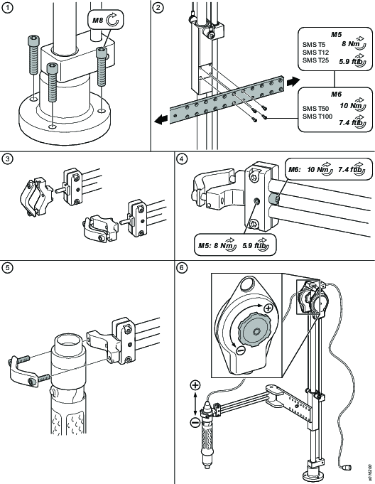
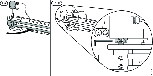
Put the encoder with coupling on the shaft at the top of the vertical arm.
Tighten the flanges with the screws.
Carefully tighten the clamping hup with the screw.
Fasten the protection over the encoder with the screws.
Connect the encoder to the Turck I/O Module.

Installing the torque arm attachment
Before you start the installation, measure the applicable position of the torque arm for your working area.
Fasten the torque arm base with screws (not supplied) on a horizontal bench. Tighten the screws until the torque arm is properly seated.
Fasten the horizontal arm on the vertical arm with the screws. Select the applicable holes on the arm for optimal operation within your working area.
Choose the tool holder orientation.
Fasten the tool holder at the end of the horizontal arm with the screws. Tighten the screws with the recommended torque.
Attach the tool to the tool holder on the recommended tool clamp area with the screws. Tighten the screws to the recommended torque. For more information about correct tool clamp area and recommended torque, see the applicable tool Product Instruction or contact your local Atlas Copco representative.
Set the balancer. Turn the wheel on the balancer to get the optimum resistance (depending on the tool). The tool can at this time be connected to the power supply.
Product Specifications
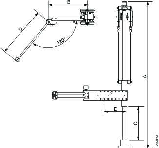
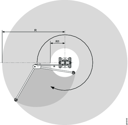
Model | Art number | Torque Max |
| A |
|
|---|---|---|---|---|---|
|
| Nm | ft.lb | mm | in |
SMS T5 Position | 4390 2036 00 | 5 | 3.7 | 789 | 31.1 |
SMS T12 Position | 4390 2037 00 | 12 | 8.9 | 945 | 37.2 |
SMS T25 Position | 4390 2038 00 | 25 | 18.4 | 1189 | 45.6 |
SMS T50 Position | 4390 2039 00 | 50 | 36.9 | 1189 | 45.6 |
SMS T100 Position | 4390 2040 00 | 100 | 73.8 | 1189 | 45.6 |
Model | Art number | B |
| C |
|
|---|---|---|---|---|---|
|
| mm | in | mm | in |
SMS T5 Position | 4390 2036 00 | 248 | 9.76 | 241 | 9.49 |
SMS T12 Position | 4390 2037 00 | 298 | 11.73 | 396 | 15.59 |
SMS T25 Position | 4390 2038 00 | 296 | 11.65 | 551 | 21.69 |
SMS T50 Position | 4390 2039 00 | 336 | 13.23 | 489 | 19.25 |
SMS T100 Position | 4390 2040 00 | 391 | 15.4 | 471 | 18.54 |
Model | Art number | D |
| E |
|
|---|---|---|---|---|---|
|
| mm | in | mm | in |
SMS T5 Position | 4390 2036 00 | 292 | 11.5 | 168 | 6.6 |
SMS T12 Position | 4390 2037 00 | 342 | 13.5 | 168 | 6.6 |
SMS T25 Position | 4390 2038 00 | 392 | 15.5 | 168 | 6.6 |
SMS T50 Position | 4390 2039 00 | 440 | 17.3 | 228 | 9 |
SMS T100 Position | 4390 2040 00 | 490 | 19.3 | 228 | 9 |
Model | Art number | R |
| R1 |
|
|---|---|---|---|---|---|
|
| mm | in | mm | in |
SMS T5 Position | 4390 2036 00 | 489 | 19.25 | 140 | 5.5 |
SMS T12 Position | 4390 2037 00 | 575 | 22.63 | 146 | 5.8 |
SMS T25 Position | 4390 2038 00 | 621 | 24.45 | 183 | 7.2 |
SMS T50 Position | 4390 2039 00 | 698 | 27.5 | 154 | 6.1 |
SMS T100 Position | 4390 2040 00 | 788 | 31 | 158 | 6.2 |
Model | Art number | Tool weight |
|
|---|---|---|---|
|
| kg | lbs |
SMS T5 Position | 4390 2036 00 | 0.8 | 1.76 |
SMS T12 Position | 4390 2037 00 | 1.5 | 3.3 |
SMS T25 Position | 4390 2038 00 | 2.5 | 5.5 |
SMS T50 Position | 4390 2039 00 | 5 | 4.85 |
SMS T100 Position | 4390 2040 00 | 6 | 11 |
|
|
|---|---|
A | Height |
B | Widht |
C | Vertikal stroke |
D, R,R1 | Radius |
E | Fixed stroke |
Service
Maintenance Instructions
Connecting the Turck I/O Module
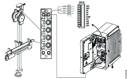
Settings for horizontal arm rotary analog encoder
The analog encoder is already set in plant. This calibration process is only for maintenance purpose.
Calibration
Connect the encoder to the Turck I/O Module.
Lubrication Instructions
Lubrication
We recommend that the bench stand pole is lubricated with a couple of drops of oil twice a year.
The bushings on the arms does not need to be lubricated.